
Wind Tunnel |
|
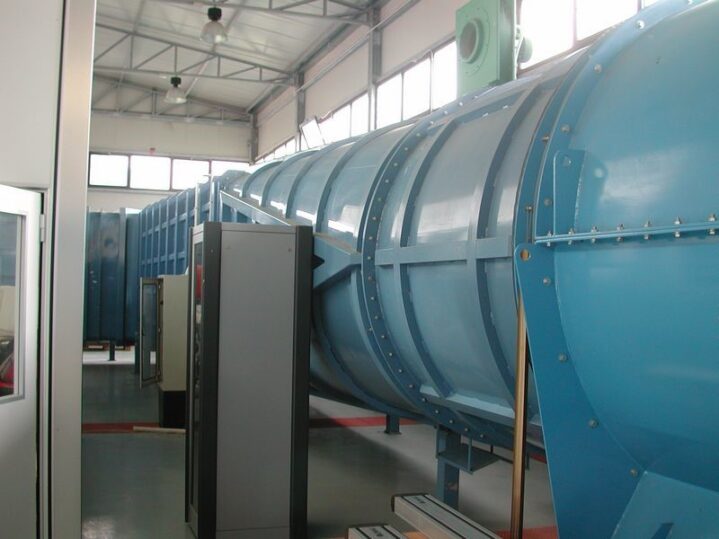 |
The ENEA Wind Tunnel is a research infrastructure located inside the Casaccia Research Center, situated on Via Anguillarese, northwest of Rome.
This facility is used to carry out experimental research activities as well as fluid dynamics and aerodynamic tests. Among its key applications and recent projects, the following stand out: Aeronautical Sector: Development of innovative technologies for aircraft control surfaces and components. For instance, it was utilized within the DAVYD collaborative project to test wing models and landing configurations through dedicated observation windows (e.g., made of Kevlar). Energy and Structural Engineering: Testing of airflow and aerodynamics applied to energy components (such as profiles for solar or wind energy) and analyzing the behavior of structures under wind loads. The wind tunnel operates in synergy with local universities and research centers (such as collaborations with Roman universities) for advanced numerical and experimental validations. The ENEA Casaccia Research Center Wind Tunnel is primarily structured as an experimental facility for subsonic flows, designed for fluid dynamics validation, industrial aerodynamic testing, and energy research (e.g., concentrated solar power and wing components). The technical architecture and instrumentation of the facility include: Fluid Dynamics Architecture Flow Regime: The facility operates under a subsonic and incompressible regime, ideal for simulating atmospheric boundary layer conditions, terrestrial aerodynamics, and takeoff/landing configurations in the aeronautical field. Flow Conditioning: Air is channeled through a settling chamber and a contraction cone. At the end of the contraction cone, the flow passes through honeycomb flow straighteners and wire meshes to damp residual turbulence, ensuring maximum laminarity and velocity uniformity at the test section inlet. Instrumentation and Measurement Systems The wind tunnel integrates sensors and data acquisition systems to map pressure fields and the forces acting on the models: Anemometry and Velocity: Pitot-Prandtl tubes and high-precision differential manometers are used to detect dynamic pressure and calculate flow velocity at any point in the stream. For advanced turbulence and vorticity analyses (e.g., wake profiles or barriers), the facility supports Laser Doppler Anemometry (LDA) systems. Force Measurement: Structural or aerodynamic models (such as heliostats for concentrated solar power or wing profiles) are mounted on strain-gauge aerodynamic balances. These allow for the measurement of pressure distribution, lift/drag forces, and resulting moments as the angle of incidence varies. Environmental Monitoring: The chamber is fully instrumented for continuous monitoring of temperature, relative humidity, and atmospheric pressure—key parameters used to correct air density (ρ) when calculating dimensionless aerodynamic coefficients. Digital Integration and Control: The motion systems (such as the turntable for model orientation relative to the flow) and the fan drive are managed by an integrated digital control platform. This allows for automated test cycles, synchronizing fan power adjustments and wind angles of attack with sensor data acquisition. |
Hydrodynamic channel |
|
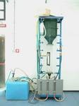 |
The vertical fluid dynamics educational or bench module (specifically configured for simulating and measuring flows within ducts or channels), closely related to systems used for studying hydrodynamics and hydraulics in school or university laboratories.
The system consists of a self-supporting vertical structure equipped with a central transparent duct (measurement column), paired with an external blue tank at the bottom for fluid supply, liquid recirculation, and flow rate control via a dedicated pump. Through this type of instrumentation, it is possible to perform several fundamental fluid dynamics and hydrodynamic experiments:
|
Anechoic chamber |
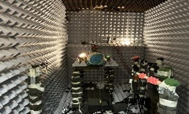
| The Anechoic chamber used in the “G. Guj” Fluid Dynamics Laboratory at Roma Tre University is a state-of-the-art facility designed for experimental research in aeroacoustics.
Its primary technical specifications and configurations include: Acoustic Architecture and Treatment Facility Type: It is configured as a semi-anechoic chamber, featuring walls and a ceiling lined with sound-absorbing materials (such as geometric acoustic wedges or panels) engineered to eliminate sound wave reflections, while the floor remains acoustically rigid (reflective) to stably support heavy machinery and structural rigs. Isolation and Echo Damping: The chamber is designed to minimize external background noise and to simulate acoustic free-field conditions within the upper hemisphere. Test Configurations and Objectives The chamber is directly integrated with fluid dynamics facilities to conduct joint studies on flow fields and radiated acoustic fields. Specifically, it is used for: High-Speed Jets: Researching the aeroacoustics and aerodynamics of turbulent circular jets under both incompressible and compressible conditions (up to high-speed regimes). Wall Flows and Cavities: Analyzing noise generated by fluid flow over flat surfaces or inside deep and shallow cavities, which is highly relevant for reducing fuselage and landing gear noise in aircraft. Propulsion and Propellers: Characterizing the radiated noise from small propellers used in aeronautics and drones (UAVs), as well as the aerodynamics of industrial and automotive fans. Laboratory Instrumentation and Sensors Advanced data acquisition systems operate inside and alongside the chamber: Acoustic Detection: The facility utilizes microphones for measuring fluctuating pressures, along with complex microphone arrays for the spatial localization of noise sources via beamforming techniques. Synchronized Fluid Dynamics Measurements: The laboratory couples acoustic testing with flow velocity measurement techniques, such as Hot-Wire Anemometry (HWA), as well as non-intrusive optical systems like Particle Image Velocimetry (PIV) and BOS Schlieren flow visualization. The gathered data are subsequently processed using advanced time-frequency analysis methods (such as spectral decompositions) to investigate how turbulent flow structures transform into acoustic waves. |
Compressible single-stream jet |
|
 |
The compressible single-stream jet facility used for aeroacoustic research by Professor Matteo Mancinelli and Professor Roberto Camussi inside the “G. Guj” Fluid Dynamics Laboratory at Roma Tre University is a high-performance experimental setup specifically engineered to investigate turbulent jet noise and its interaction with solid aerodynamic surfaces (such as plates or wing models).
The primary technical characteristics of the jet facility and its supply line include:
|
Instrumentation |
|
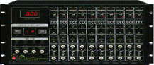
The A.A. Lab Systems AN-1003 is a high-performance hot-wire and hot-film anemometry system built to measure fluid and gas velocities. Key Features
|
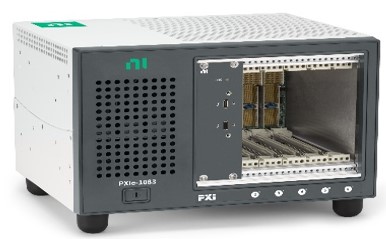 National Instruments:
Yokogawa:
The combination of the NI PXIe-1083 chassis and the NI PXIe-6349 data acquisition board forms a compact, high-performance system for testing, measurement, and industrial automation, controllable directly from a PC or laptop. The main advantage of this specific setup is that the chassis already includes a built-in bus controller based on Thunderbolt 3 technology, removing the need for a |
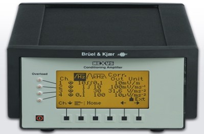
Signal conditioner B&K NEXUS 2690
Signal conditioner Kulite KSC2-C3 2 microfoni Kulite mic-190M The Brüel & Kjær NEXUS (Type 2690–2693 series) is a 1 to 4-channel modular and reconfigurable signal conditioning amplifier designed for acoustic and vibration measurements in both the field and the laboratory. |
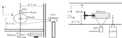
LDA (Laser Doppler Anemometry) and PIV (Particle Image Velocimetry) are two of the most widely used non-intrusive experimental optical techniques in fluid dynamics to measure fluid velocity. Both require seeding the fluid with tiny tracer particles illuminated by a laser, but they differ fundamentally in their spatial and temporal approaches. When to choose one over the other? LDA is preferred when it is essential to analyze the turbulence frequency spectrum at a precise point or to accurately validate local velocity profiles. PIV is preferred when the goal is to visualize macroscopic flow structures, such as vortex formation, recirculations, or the temporal evolution of a wake. |